LDV (Laser Doppler Velocimetry) Principle
Laser Doppler Velocimetry (LDV) is a laser-based method used to extract the velocity at a given point, whether in a flow or on a solid surface. The principle of LDV is not difficult to grasp once you understand the nature of coherent laser light, which travels with its wavefronts parallel and "in synch" with eachother.
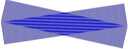
There are several ways to describe how LDV works. The method described here uses the description of fringes. When 2 coherent, collimated laser beams intersect, they form a fringe pattern. This process can be illustrated by 2 "beams" of parallel lines that intersect, like in the illustration to the right. At the point where the beams intersect, the wavefronts interact with eachother constructively or destructively and form a pattern of horizontal lines that were not present until the beams intersected. This is the fringe pattern.
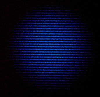
An actual fringe pattern can be seen in the image to the left. This represents a cross-sectional view of the previous figure. Imagine that a particle in the air or water passes through this fringe pattern from top to bottom. As it travels, it alternately reflects the light (as it passes through a fringe), and does not reflect light (as it passes between fringes). A signal detector that is focused on the beam crossing can pick up these minute flashes of light and determine their frequency. Once the frequency of these flashes of light is known, it is multiplied by the distance between the fringes to get the velocity. (Velocity = Distance/Time = Distance*Frequency)
An LDV system consists of the following components: a laser, a beam separating device, a transceiver (which emits the laser beams and also collects the reflected signals), a photomultiplier unit to convert the optical signal to an electrical signal, a signal processor, and software to analyze the results.
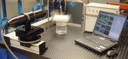
An LDV system can be seen in the figure to the right. The laser is the orange box out of view in the upper right-hand corner. The beam separating optics is not shown, the transceiver is the black probe in the foreground on the left-hand side. If you look carefully, you can see the beam crossing at the center of the water spray coming in from the top of the image. Since this is a 2 component LDV system, there are 4 laser beams, 2 green and 2 blue, that all cross at the same point. Filters in the PMT box (top box behind the computer) filter the 2 colors of light and pass them through to be converted to electrical signals. The bottom box is the signal processor, which analyzes the LDV data and gives useful results, namely, velocity.
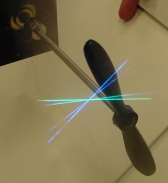
LDV can also be expanded to measure the velocity in 3 dimensions. In this case, you typically have 6 laser beams all crossing at a common point (2 beams for each component). In this case, the alignment of all 3 components is critical in order to be sure you are measuring the velocity of a single particle in 3 directions simultaneously. The beam crossing of a 3-component LDV system can be seen in the image to the left measuring the velocity of the airflow around a small propeller. The colors used in this case are green (514.5 nm), blue (488 nm), and violet (476.5 nm). (From this angle, the green beams are nearly overlapping the blue beams.) The seeding particles in this case are water droplets from an ultrasonic humidifier, which are several hundred nanometers in diameter.
To download a poster from TSI with lots of nice graphics explaining the LDV technique, click here.