GSV (Global Sizing Velocimetry) Principle
Global Sizing Velocimetry (GSV) is a laser-based technique (interferometric-based) in which a camera is used to extract size and velocity information from an out-of-focus image of a field of particles.
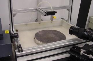
A GSV system is seen in the image to the right. It includes a dual-head Nd:YAG pulsed laser with vertical polarity, light sheet optics to form a light sheet from the circular laser beam, a camera set at 60 degrees from the forward scatter direction of the laser sheet, and a slit in front of the camera lens to optimize the measurement (more about this later). In addition to these components, there is a synchronizing device to take care of the timing of the laser pulses and the camera exposures, and software to analyze the data.

First a couple of comments on the interferometric technique. When the laser light strikes a droplet, the light is scattered toward the observer in several ways. It is reflected off of the surface of the particle, and it is refracted inside the particle and internally reflected. The image to the left shows a stream of droplets that are illuminated by a light source coming from the right-hand side of the image. Looking closely, you notice that each droplet in the image doesn't appear circular, rather, it is represented by 2 dots of light, one from the reflected light and one from the internally reflected light.
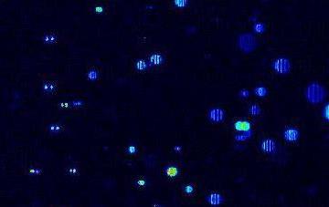
The image to the right shows a GSV image where the left side of the image is in focus on the particles. The right edge of the image is not in focus, since the camera is at 60 degrees to the light sheet. The particles on the right are out-of-focus, since they are in front of the focus plane of the camera. If you look very closely, you can see that at the left side of the image, you are seeing in-focus particles that look like 2 dots. As you go from the left to the right side of the image, the 2 dots merge together and interfere with one another, creating an interference fringe pattern. (Room light will not create a fringe pattern, since it is not "coherent.") The spacing of the fringes is inversely proportional to the size of the droplet, therefore, if we can accurately measure the distance between the fringes, then we can determine the particle diameter.
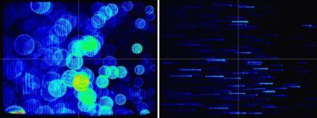
Current Interferometric systems use a slit in front of the lens to decrease the amount of overlap among particles. The image to the left compares GSV images with and without a slit. You can see that the image with the slit (right side) makes it possible to measure sprays that are much more dense. Since you only need to be able to calculate the fringe spacing (the size of the out-of-focus image does not contain any actual size information), a slit works just as well as the entire circle in determining the droplet size.
After the slit is put in place, and you begin taking images of a spray, the images display a horizontal line with dots (the fringes) for each particle. From this point software is used to analyze the images by identify each droplet, performing FFT analysis on the fringe spacing, and also determining the velocity by comparing the image with one taken right after it and performing particle tracking.
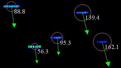
The image to the right is a zoomed-in view of a typical GSV image that has been analyzed. The numbers reflect the calculated droplet size in microns, and the arrow represents the velocity.
GSV can measure droplet size in the range of about 10 microns to 800 microns. The field of view is on the order of the size of the camera CCD array, a typical example would be about 15 mm square.