Detached eddy simulation
Aerodynamic heating greatly affects the overall design of
aerospace vehicles. Most research has focused on the
forebody flow that is characterized by high levels of radiative and
convective heating. However, the flow on the afterbody of the vehicle
also results in significant aerothermal loads. In contrast to a laminar
boundary layer on the forebody, the flow in the large wake region
enclosing the afterbody can be transitional or
turbulent. Turbulent mixing often alters the structure of the wake and
enhances the heat transfer to the vehicle considerably.
Until recently, engineering prediction of turbulent flows
relied exclusively on Reynolds-averaged Navier Stokes (RANS)
simulations that compute the time-averaged flow field. However, RANS
turbulence models yield large errors in regions of large-scale
separation. The inaccuracies in predicting turbulent heating rates are
generally compensated by a large safety factor in the design of
afterbody heat shields. Detached eddy simulation (DES) significantly
improves predictions in massively separated flows by simulating the
unsteady dynamics of the dominant length scales. DES has mostly been
used in low-speed flows, with limited application at supersonic speed.
We use detached eddy simulation to study the flow field
at the base of the Fire II re-entry vehicle. Project Fire flights were
conducted to investigate the heating environment on a blunt-nosed,
Apollo-shaped vehicle entering the earth's atmosphere at a velocity in
excess of the escape velocity. We simulate the conditions at a point in
the later part of the trajectory where the freestream Mach number is 16
and the Reynolds number based on the body diameter is 1.76E6. The
figures below show a schematic of the vehicle and the computed
temperature field around it.
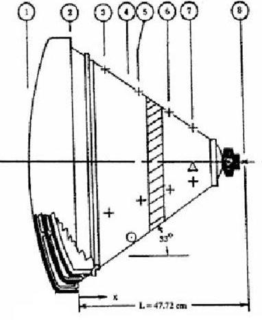
The
figures above show a schematic of the vehicle and a snapshot of the
computed
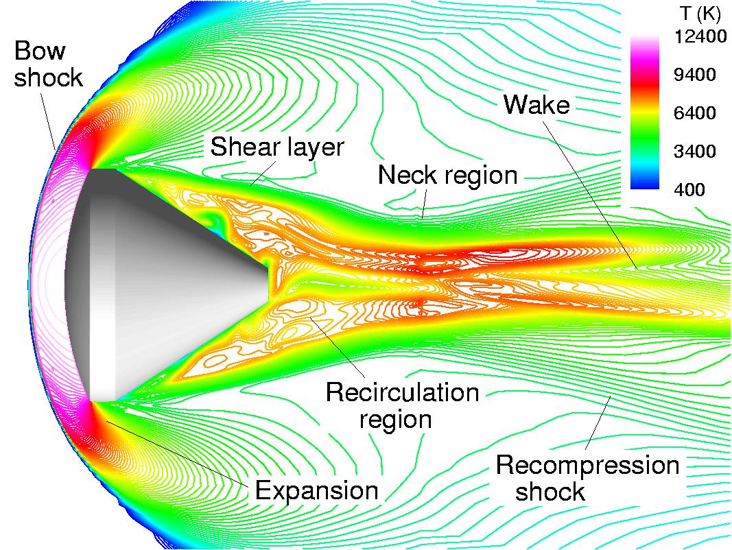
temperature field around it. The freestream flow is from left to right,
and is slowed down by the bow shock ahead of the body. The flow expands
around the corners and separates to form a large recirculation
region behind the vehicle. The flow in this region is highly
unsteady and three - dimensional with a large range of length and time
scales. The shear layers enclosing the recirculation region come
together at the neck region. A recompression shock is formed at this
point that turns the outer flow to make it parallel to the vehicle axis.
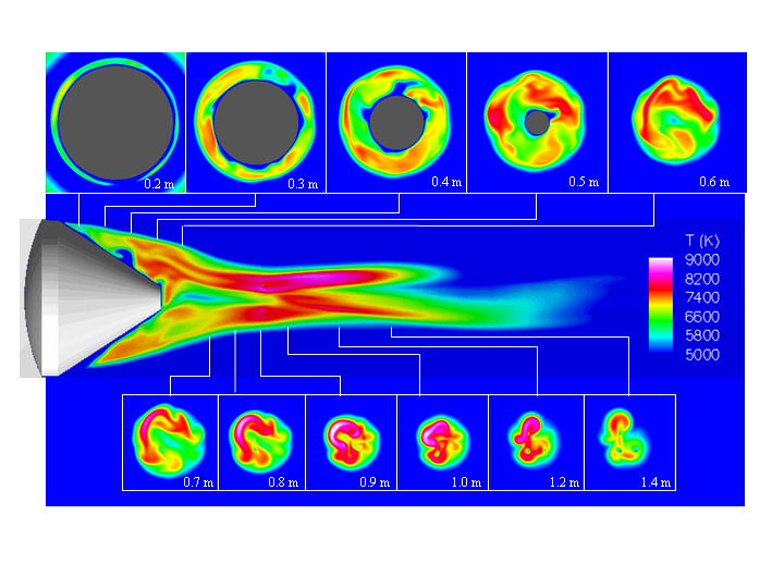
The figure below presents the temperature distribution in
an axial plane as well as several cross-sections through the wake. The
temperature in the recirculation region varies between a cooled wall
temperature of 553 K and a maximum of about 9000 K in the neck region.
There is a low temperature region next to the wall that corresponds to
a laminar boundary layer. Some of the cold fluid from this region is
swept away from the wall. The temperature increases as the size of the
recirculation region reduces up to the neck region. The highest
temperature is found in the neck region due to the recompression shock.
Downstream of the neck, the wake expands and the temperature drops
considerably.